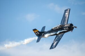
The wing has two vortices: the well-known wingtip vortices and the not-well-known, except to aeronautical engineers, wing-sheet vortices. The latter vortices are also known as wake vortices, wing vortices, and downwash. Unfortunately, many wrongly believe wingtip vortices and wing-sheet vortices are the same. They are not as will be explained on this webpage.
Wingtip Vortices
Wingtip vortices are the only vortices that most people connect with the wing. It is produced by the communication around the wingtip of the high pressure below the wing with the low pressure above the wing. See Figure 1. It is a tight curling of the air and is often very visible, such as in Figure 2.
All wings move through still air. If that seems odd to you, read the Still Air webpage for a full discussion. The wingtip vortex forms a curl in that still air. When the humidity is high, the pressure drop causes a temperature drop, resulting in condensation that makes the curl visible. The wing continues forward, leaving the curl behind like a trail of smoke. There is essentially no energy in the vortex left behind.
It is commonly believed that wingtip vortices rotate. They do, while at the end of the wing. Here, the rotation is powered by the difference in pressure between the top and bottom of the wing. After the wing leaves the curl behind, there is no longer any power to maintain the rotation, and a nice circle remains in the still air. The wingtip vortices are a nice string of these circles.
Wingtip vortices are wrongly given credit for the energy loss in lift, the production of induced drag, tilting downwash, ground effect, the need to increase angle of attack, and more myths, including the hazard of flying behind another airplane. The reality is that wingtip vortices are a wimp with very little energy and effect.
Wing-sheet vortices are the powerhouse that can cause aircraft upset and controllability problems. The power of wing-sheet vortices exists because an airplane accelerates many tons of air per second to produce lift.
Since the wing is moving through still air, the wingtip vortices remain where they formed and are left behind like a trail of smoke. The wingtip vortices are also believed to combine with the curling of the downwash sheet, i.e., the wing-sheet vortices. This is not so, as shown in the four images in Figure 3. Note that images A, B, and C show both the wingtip vortices and flap vortices. A Flap vortex is produced at the outer edge of the wing flap and is part of the wing-sheet vortices and will be discussed below. Image D shows wingtip vortices as well as the effect of wing-sheet vortices on the clouds. It’s a big step to claim that the wingtip vortices made the large curls in the clouds. The downwash is accelerated in the production of lift while the wingtip vortices are just left behind.
Wing-Sheet Vortices
(a.k.a. Wing Vortices, a.k.a. Downwash)
Now we come to the real heavy lifter of flight: the wing-sheet vortices. One must remember (Lift on a Wing) that a small general aviation aircraft like a Cessna 172 has wing-sheet vortices diverting over a ton of air per second. The wing-sheet vortices of a commercial jet can be on the order of 100 tons per second.
Figure 4 shows the airflow behind a wing with a winglet. Figure 5 shows the airflow a short distance farther back for wings with and without winglets. Note the lift distribution (the variation of lift across the wing) on the wing. The curl in the downwash is due to the rate of change in the mass and speed of the downwash. The greater the change, the sharper the curl. For a clean wing in flight, that is a wing without flaps or slats deployed, the greatest change is at the tip of the wing where the lift abruptly goes to zero. Figure 6 shows an airplane landing with its flaps down. The outer edge of the flap has the greatest change in lift and thus is the producer of the visible part of the wing-sheet vortices.
Figure 6 is a good example of flap vortices. The condensation on top of the wing shows the lift distribution on the wing. One can see that it drops off rapidly at the end of the flap. With the flaps down, there is little lift outboard of the flap. In the picture, you might be able to see just a wisp of a wingtip vortex on the tip of the right wing.
Figure 7 shows a simulation of the input to the circulation of a T-tail sailplane. The red lines represent where the curl is coming from. The blue arrows represent the lift. There is circulation at the wing root because the lift drops off at the fuselage. Note that the circulation comes in as it goes back. Where there is no circulation because the lift is relatively constant across that part of the wing, the downwash goes almost perpendicular to the flight path. Figure 8 shows a simulation of the development of the curl in the wing vortex. This simulation is nicely confirmed by the wing vortices curled in the clouds left by an airplane. The curl on the left certainly resembles the simulation. The air between the spirals is perpendicular to the flight path.
Figure 9 shows the spirals in the clouds and the flap vortices. Wingtip vortices are never included in the wing vortex curl. Figure 10 shows two examples of curls in wing-sheet vortices. Figure 11 shows the depression in the clouds from the downwash of two planes flying over the clouds. The first picture is of a Russian Bear.
Winglets
Winglets are like small wings placed on the end of a wing to improve efficiency, but not for the reason many people think. There are many styles of winglets. Figure 12 shows three examples. Figure 12A is a Blended winglet (Airbus), 12B is a Split-Simitar winglet (Boeing 737 Max), and 12C is a Folding winglet (Boeing 777X).
Winglets are said to increase fuel efficiency by 1.5-2% on longer flights. Boeing says that the Split-Simitar increases fuel efficiency by 1.5%. Winglets can cost over half a million dollars each but can save an airline $200 million a year in fuel for the fleet.
The common belief is that winglets improve efficiency by reducing the energy in the wingtip vortices, as illustrated in Figure 13. But we have already seen that there is very little energy in wingtip vortices. So that could not account for the relatively large improvement in efficiency.
The improvement is due to the redistribution of lift. This is illustrated in Figure 14. The red line shows the lift distribution of a straight wing. The lift must go to zero at the wing tip. The yellow line shows the lift distribution for a wing with a steep winglet, and the blue line for a wing with a winglet at a slightly smaller angle. Notice that the lift distributions with the winglets are not zero at the end of the wing. This extended lift distribution is equivalent to having a longer wing. A longer wing is more efficient for lift. Roughly, the effect is the same as having a wing extended about half the length of the winglet. This is a considerable gain since winglets can be 10 feet or longer.
One of the driving forces for winglets is that they are considered “sexy”. When Boeing wanted to make a business version of the 737BBJ (Boeing Business Jet), they wanted to use winglets. At first, the FAA had trouble with the approval since the 737 hadn’t been tested for the modified lift distribution. Eventually, the BBJ was approved because the business jet would not have the hours of a jet for the airlines
Downwash Hazard
The downwash of a large airplane can be very hazardous to following airplanes, particularly near the ground. The three conditions that make for the greatest hazard are when the airplane is heavy, clean, and slow. On takeoff, the airplane is at its heaviest with full fuel. Shortly after leaving the ground, the pilot retracts the slats and flaps so that the wings are “clean”. Also, just after the airplane “rotates,” it is going slowly. Remember that a large airplane is accelerating 10’s of tons of air per second. On landing, the airplane is still heavy and slow, but the wings are not clean. There is still danger in following too closely.
The wing-sheet vortex of an airplane can roll other aircraft following too close. An accident report of such an event can be found at the end of this section. Near the ground, the wing-sheet vortices sink at about 4 mph. This is illustrated in Figure 15. On takeoff, following a “heavy” one should move to the upwind side of the runway for safety.
Accident Report 1
Following an uneventful flight from San Luis Potosí, the crew was cleared to the MATEO VOR and for an ILS/DME approach to runway 05R at Mexico-Benito Juarez Intl Airport, then was instructed by ATC to increase their speed to 220 knots. The Learjet was trailing a Boeing 767-300. The controller instructed the Learjet crew to reduce their airspeed to 180 knots. This was acknowledged, but it took 16 seconds for the crew to take action. The separation between the Boeing 767 and Learjet had decreased to 3.8 NM, and the Learjet entered the wake turbulence of the 767. Control was lost, and the aircraft entered an uncontrolled descent and crashed. The aircraft disintegrated on impact, and all 9 occupants were killed, as well as 7 people on the ground. Some buildings were damaged, about 20 cars were destroyed, and 40 people on the ground were injured, some seriously.
https://www.baaa-acro.com/crash/crash-learjet-45-mexico-city-16-killed
Probable cause:
Loss of control at low altitude and subsequent impact of the aircraft with the ground after it encountered wake turbulence caused by a preceding aircraft.
Accident Report 2
A wake vortices accident occurred when a Bombardier Challenger 604 encountered the wake vortices from an Airbus A380. The 604 rolled multiple times, passengers sustained numerous injuries, and the aircraft suffered severe structural damage, resulting in it being scrapped. Click the above link for a full report.
